Note also that this relation is quite independent of the characteristic impedance of the line, a property that is very useful in practice. Note that there is no contradiction here, since all normalized quantities are dimensionless. Both must be normalized with respect to the line. It states that if a Quarter Wavelength Transmission Line is connected to an impedance, then the normalized input impedance of this line is equal to the normalized load admittance.

Where y L is the normalized admittance of the load.Įquation (7-12) is a very important relation. Substituting these results into Equation (8-11) gives The relation holds just as well when the two points are not voltage nodes and antinodes, and a glance at Figure 7-9 shows that it also applies when the distance separating the points is three, five, seven and so on, quarter-wavelengths.Īnother interesting property of the Quarter Wavelength Transmission Line is seen if, in Equation (7-10), the impedance are normalized with respect to Z 0. Equation (7-10) states this relation mathematically and also supplies the proportionality constant this happens to be the square of the characteristic impedance of the transmission line. This amounts to saying that the impedance at A is inversely proportional to the impedance at B. Thus an increase in Z B is accompanied by a decrease in Z A (if A and B are λ/4 apart). The size of the voltage maximum at B would be increased, and so would the impedance at B. If the SWR were increased, the voltage minimum at A would be lower, and so would be the impedance at A. In order to change the impedance at A, it would be necessary to change the SWR on the line. It is obvious that at the point A (voltage node, current antinode) the line impedance is low, and at the point B (voltage antinode, current node) it is the reverse, i.e., high. Note also that the current nodes are separated from the voltage nodes by a distance of λ/4, as before. Note that here the voltage and current minima are not zero the load is not a short circuit, and therefore the standing-wave ratio is not infinite.

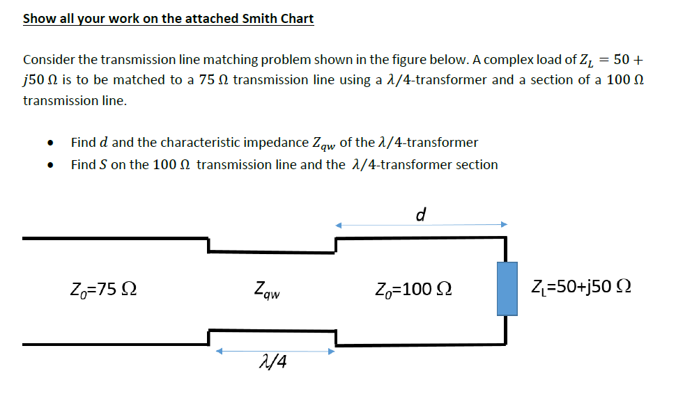
This has already been shown and is indicated again in Figure 7-9. Unless a load is resistive and equal to the characteristic impedance of the line to which it is connected, standing waves of voltage and current are set up along the line, with a node (and antinode) repetition rate of λ/2. Equation (7-10) represents a very important and fundamental relation, which is somewhat too complex to derive here, but whose truth may be indicated as follows. This relationship is sometimes called reflective impedance i.e., the Quarter Wavelength Transmission Line reflects the opposite of its load impedance. When the length s is exactly a quarter-wavelength line (or an odd number of quarter-wavelengths) and the line is lossless, then the impedance Z s, seen when looking toward the load, is given by Impedance inversion by Quarter Wavelength lines:Ĭonsider Figure 7-8, which shows a load of impedance Z L connected to a piece of transmission line of length s and having Z 0 as its characteristic impedance.


 0 kommentar(er)
